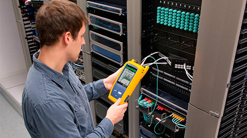
Most OTDRs are designed for a myriad of applications, causing the user interface to be difficult to navigate and interpret. OptiFiber Pro combines the latest "gesture-based" interface technology with a capacitive touchscreen to deliver the most innovative and user-friendly OTDR.
Advantages:
Single-touch tap and swipe control for selecting and scrolling menu items
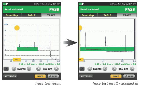
Multi-touch pinch to zoom for easy magnification control on a graphical fiber trace
Task-focused design to reduce back and forth navigation through screens
Capacitive touchscreen eliminates the need to recalibrate unlike legacy touchscreens
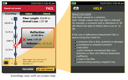
Context sensitive on-screen help that gives users additional details or problem resolution suggestions
Optimized for the Datacenter
Driven by server virtualization and multi-gigabit links between servers, networks and storage, the datacenter architecture employs more patch cords and dense topology connectors, rendering carrier-class OTDRs with long dead zones ineffective. OptiFiber Pro not only makes fiber deployment in datacenters possible, but provides the highest level of accuracy for quick problem resolution.
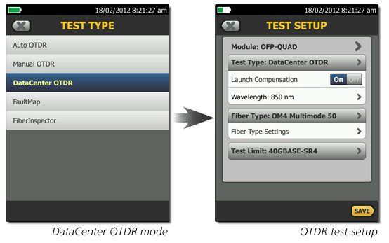
With a simple one-touch selection, users enter DataCenter OTDR mode - without setup time for fine-tuning as needed in legacy OTDRs. DataCenter OTDR mode automatically detects OTDR parameters - end-detection algorithms, pulse widths, etc - without getting confused by the short links or number of connectors.
Advantages:
Ultra-short event and attenuation dead-zones precisely locates events and faults on fiber links
DataCenter OTDR™ mode automatically sets the configuration to quickly test datacenter fiber
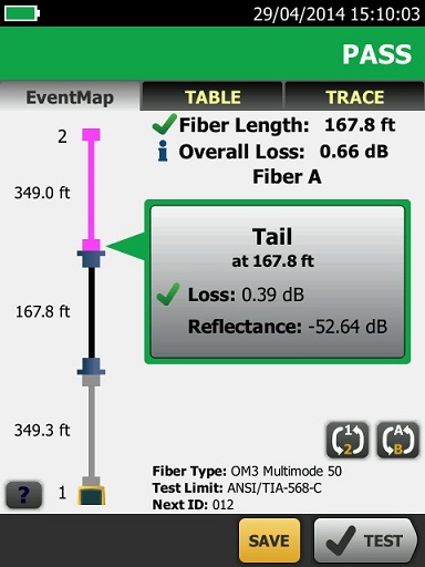
The EventMap feature depicts fiber events in a way that requires no trace analysis expertise
SmartLoop OTDR
SmartLoop OTDR enables automated testing and analysis of two fibers in a single test. This patent pending process automatically separates the two fibers for individual pass/fail analysis, display, and reporting. Not only does this cut the testing time by at least half, it also enables bi-directional testing without moving the OTDR to the far end. In addition to getting the job done quicker, SmartLoop OTDR further enhances the ease and speed of testing in environments where the far end is difficult of even dangerous to reach because the OTDR never has to be moved to the far end.
Unique Certification with Fexibility and Efficiency
An important aspect in maximizing an OTDR's value is to properly plan its day-to-day usage. With built-in project management, OptiFiber Pro allows a project manager to define each user's role, settings and the associated tasks to be performed �V transforming the OTDR into an all-in-one fiber testing tool complete with planning, inspection, certification and reporting.
OptiFiber Pro enhances job efficiency by allowing the workflow planner to create and manage operator and job profiles per project - defined jobs or sets of cable IDs can be assigned to specific operators. The progress and status of each project can also be easily monitored.
Advantages:
Full OTDR capability that certifies fiber performance based on job assignment for each operator
Powerful project management facilitates OTDR sharing with clear job assignment for each operator
Easy monitoring of job progress with pass/fail results
On-screen report generation and upload to LinkWare™ application
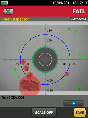
FiberInspector™ Pro
OptiFiber Pro incorporates the FiberInspector Pro video inspection system which enables you to quickly inspect and certify fiber end-faces inside ports or patch cords. It��s 2-second automated PASS/FAIL certification, per IEC 61300-3-35, eliminates human subjectivity and enables anyone to become a fiber inspection expert. Results can be saved in the certification report alongside OptiFiber Pro's OTDR results.
Other Key Features
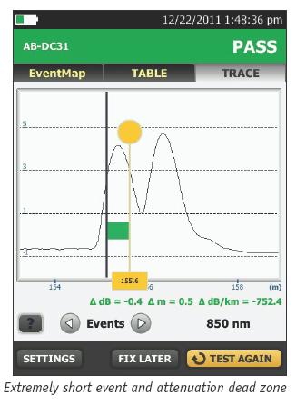
Extremely short event and attenuation dead zone
The OptiFiber Pro leverages the most sophisticated optical technology to provide the shortest event dead zone (0.5 m typical for MM) and attenuation dead zone (2.2 m typical for MM and 3.6 m typical for SM) of any OTDR. This technological advancement allows OptiFiber Pro to detect and measure closely spaced faults where no other OTDR can in today��s connector-rich datacenter and storage area environments.
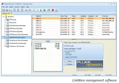
LinkWare™ management software
Leveraging the popular and multi-featured LinkWare cable test management software application, OptiFiber Pro users can easily access the hassle-free project management, report generation, and software upgrade capabilities to manage workflow and consolidate test results.
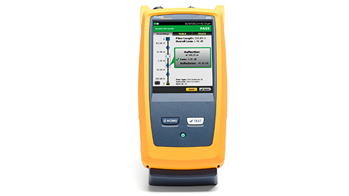
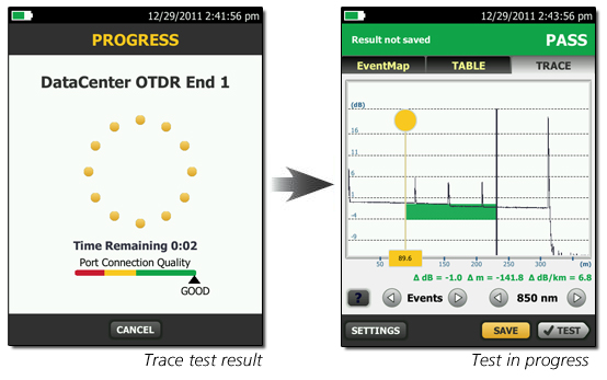
Two second trace per wavelength
Another breakthrough with OptiFiber Pro is the data acquisition speed. While in Quick Test mode, a complete set of data is acquired in as little as two seconds per wavelength. OptiFiber Pro then analyzes the data and displays it as an EventMap, Table or Trace. The end result is less time spent testing and more time performing other tasks.
Two second trace per wavelength
On-screen "help" suggests corrective action(s) for resolving fiber problems during each testing step. The "help " offered is context sensitive which allows users to quickly pinpoint possible resolutions. An easy-to-read, grey icon in the bottom, left-hand corner shows detailed corrective action recommendations.
1. Measured at 1.5 dB below non-saturating reflection peak with the shortest pulse width. Reflection peak < -40 dB for multimode and < - 50 dB for singlemode.
2. Measured at +/- 0.5 dB deviation from backscatter with the shortest pulse width. Reflection peak < -40 dB for multimode and < - 50 dB for singlemode.
3.
For typical backscatter coefficient for OM1 fiber: 850: -65 dB, 1300: -72 dB.
4. Typical backscatter and attenuation coefficients for OM2-OM4 fiber: 850 nm: -68 dB; 2.3 dB/km: 1300 nm: -76 dB; 0.6 dB/km.
5.
Typical backscatter and attenuation coefficients for OS1-OS2 fiber: 1310nm : -79 dB; 0.32 dB/km; 1550 nm: -82 dB; 0.19 dB/km.
6.
SNR=1 method, 3 minute averaging, widest pulse width.
7.
850 = 9 km typical to find the end or 7 km typical to find a 0.1 dB event (with a maximum of 18 dB attenuation prior to the event).
8.
1300 = 35 km typical to find the end or 30 km typical to find a 0.1 dB event (with a maximum of 18 dB attenuation prior to the event).
9.
1310 = 80 km typical to find the end or 60km typical to find a 0.1 dB event (with a maximum of 20 dB attenuation prior to the event).
10.
1550 = 130 km typical to find the end or 90 km typical to find a 0.1 dB event (with a maximum of 18 dB attenuation prior to the event).
11.
Does not include index of refraction error and does not include automatic event location error.
12.
dB variation per 1 dB step.
13.
Applies along the trace backscatter within the distance range in which the OTDR can find a 0.1 dB event
Additional key specifications
FiberInspector probe specification
Magnification
~ 200X with OptiFiber Pro Display
Light source
Blue LED
Power source
Versiv mainframe
Field of View (FOV)
Horizontal: 425 �gm
Vertical: 320 �gm
Minimum detectable particle size
0.5 �gm
Dimensions
Approximately 6.75 in x 1.5 in (1175 mm x 35 mm) without adapter tip
Weight
200g
Temperature range
Operating: 32�XF to 122�XF (0 �XC to +50 �XC)
Storage: -4�XF to +158�XF (-20�XC to +70�XC)
Certifications
CE (when used with the mainframe)
VFL specifiations
On/Off control
Mechanical switch and a button on the touch screen
Mainframe with module and battery: 3 lbs, 5 oz (1.28 kg)
Dimensions
Mainframe with module and battery: 2.625 in x 5.25 in x 11.0 in ( 6.67 cm x 13.33 cm x 27.94 cm)
Battery
Lithium ion battery pack, 7.2 volts
Battery life
Eight hour Auto OTDR operation, dual wavelength,
no video probe connected, 150 m of fiber
Charge Time
Tester Off
Four hours to charge from 10% to 90% capacity
Tester On
Six hours to charge from 10% to 90% capacity with the tester on
Environmental specifications
Operating temperature*
-18oC to 45oC
Non-operating temperature
-30oC to 60oC
Operating altitude
4,000 m (13123 ft)
3200 m (10,500 ft) with ac adapter
Storage altitude
12,000 m
EMC
EN 61326-1
* Using battery power. With AC power: 0oC to 45oC. Real Time Trace function used for no more than 5 minutes in a 15-minute period. Maximum ambient temperature is 35oC for continuous use of the Real Time Trace function.
* Do not keep battery at temperatures below -20�XC (-4�XF) or above 50�XC (122�XF) for periods longer than one week to maintain battery capacity.
Models
OFP-CFP-Mi AP
MM OTDR + MM OLTS +
Inspection Camera
OFP-CFP-Si AP
SM OTDR + SM OLTS +
Inspection Camera
OFP-CFP-Qi AP
Quad OTDR + Quad OLTS +
Inspection Camera
OFP-100-M/AP
Versiv Main + MM 850/1300nm
OTDR Module
OFP-100-Mi/AP
Versiv Main + MM 850/1300nm
OTDR Module + Inspection Camera
OFP-100-Q/AP
Versiv Main +
Quad 850/1300/1310/1550nm
OTDR Module
OFP-100-Qi/AP
Versiv Main +
Quad 850/1300/1310/1550nm
OTDR Module + Inspection Camera
OFP-100-S/AP
Versiv Main + SM 1310/1550nm
OTDR Module
OFP-100-Si/AP
Versiv Main + SM 1310/1550nm
OTDR Module + Inspection Camera